
How to Identify Cold Solder Joints with a Multimeter
[ Back to Mechanical Keyboards 101 ]A bad solder joint can look fine and still fail a key. If I want to find it fast, I first inspect the joint, then check continuity, then check resistance, and only then reflow the spot.
Here’s the short version:
- I unplug the keyboard before testing
- I look for joints that seem dull, grainy, cracked, or rough
- I use continuity mode to see if the path is broken
- I use ohms mode to catch a weak joint that still beeps
- A solid joint usually reads near 0 Ω
- A weak joint may still pass continuity but show 10 Ω to 100 Ω
- If the reading changes when I wiggle the socket, pin, or PCB, the joint is likely bad
- On keyboard PCBs, this often shows up as dead keys, double presses, random dropouts, or a dead row/column
A few fast clues help me narrow it down:
- One dead key often points to a switch pad, diode, or socket
- A full row or column failure can point to a trace or MCU pin
- USB dropouts when the cable moves can point to the connector pins
- A diode issue may show current passing the wrong way instead of the normal 0.3 V to 0.7 V forward drop
| Check | What I look for | Bad sign |
|---|---|---|
| Visual | Smooth joint shape | Dull, gray, rough, cracked |
| Continuity | Steady beep | No beep or beep cuts in and out |
| Resistance | Near 0 Ω | >1–2 Ω, jumpy reading, or open |
| Movement test | Stable reading | Reading changes with light pressure |
Bottom line: if a suspect joint looks off, fails continuity, shows high resistance, or changes under light movement, I treat it as the fault and rework that spot with flux and heat.
That simple flow gives me a clear way to test the PCB without guessing.
Tool Tip: Check solder joints (or broken electronics) with a multimeter!
sbb-itb-3cb9615
Tools and Safety Steps Before Testing the PCB
Before you touch the PCB with a multimeter probe, set out the basics: a digital multimeter, keycap puller, loupe or magnifier, and an ESD wrist strap. Clip the wrist strap to a grounded surface before you handle the board.
Two safety rules apply every time: unplug the USB-C cable and make sure the board is fully unpowered before you probe anything. If you test a live board, you can damage both the multimeter and the PCB. Work on a well-lit bench with ventilation. Static can hit the controller or matrix diodes, so keep that ESD wrist strap on and clipped to ground.
How to Set Up Your Multimeter for Continuity and Ohms Mode
Plug the black probe into the COM port and the red probe into the V/Ω port. Set the dial to continuity mode (the continuity icon) if you want a simple beep test, or switch to resistance mode (the Ω symbol) on the lowest range, such as 200 Ω or 2,000 Ω, if you want a more exact reading .
Before the probes go anywhere near the PCB, touch them together. The meter should beep and show close to 0 Ω. If it doesn’t, check the probe ports or the battery. That quick check helps you rule out the meter as the cause of a bad reading .
Once the board is unpowered, the meter is checked, and the suspect area is marked, you can start probing.
Visual Inspection Before Probing the Board
Do a visual pass before you pick up the probes. Use the loupe to look for dull, grainy, or cracked joints.
"A good joint is smooth and shiny... A cold joint often appears dull, grainy, rough, or crystalline." - JLCPCB
Don’t try to scan the whole board in one sweep. Start with the row or column that contains the mechanical keyboard key and move outward from there. Mark the suspect joint and test that spot first.
How to Find a Cold Solder Joint Using a Multimeter
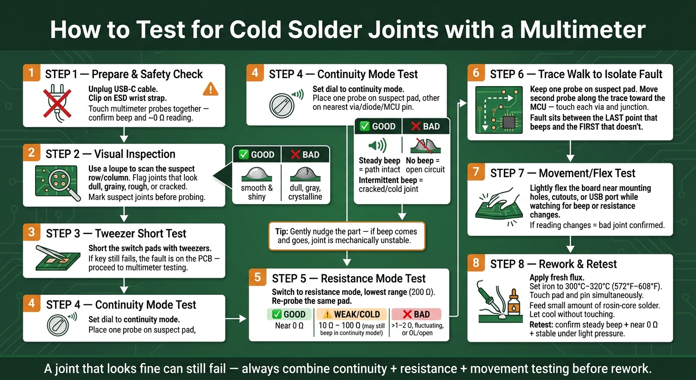
How to Test for Cold Solder Joints with a Multimeter
Start with the board unplugged and the suspect joint marked. First, confirm which key is failing in VIA or QMK. Then short the switch pads with tweezers to rule out the switch itself before you probe the PCB. If the key still doesn’t work, switch the multimeter to continuity mode.
Using Continuity Mode to Find an Open or Intermittent Connection
Put one probe on the suspect solder pad and the other on the nearest test point, like a via, diode pad, or MCU pin. If you hear a steady beep, the electrical path is intact. No beep means there’s an open circuit. If the beep drops in and out, the joint is intermittent and likely cracked or cold.
While you’re probing, gently nudge the part with tweezers. If the beep comes and goes when the part moves, the joint is mechanically unstable, even if it looks okay at a glance. That little movement test can save time. A joint can look normal and still fail the moment the board flexes.
If the reading won’t stay steady, move to resistance mode to get a clearer read on what’s going on.
Using Resistance Mode to Spot a Weak Joint
Set the meter to the lowest resistance range, such as 200 Ω. A good joint should read close to 0 Ω after you account for probe resistance. If you get several ohms, a reading that jumps around, or OL/open, that joint is suspect.
This is where resistance mode helps. A weak or cold joint may still pass continuity and beep like nothing’s wrong, but resistance testing can show 10 Ω to 100 Ω instead. That’s a red flag. Use both readings together to narrow down the exact pad or pin you should isolate next.
Comparing Continuity and Resistance Results Before Rework
Check both modes on the same pad before heating up the iron. If continuity gives a steady beep but resistance reads high, the joint is weak instead of fully open. If continuity fails and resistance shows OL, the joint is open and needs rework.
| Feature | Continuity Mode | Resistance Mode |
|---|---|---|
| What it measures | Electrical path completion (go/no-go) | Quantitative opposition to current flow (Ohms) |
| Good joint reading | Steady beep / near 0 Ω | Near 0 Ω |
| Bad joint reading | No beep or intermittent beep | > 1–2 Ω, fluctuating, or OL |
| Weak/cold joint reading | May still beep | 10 Ω to 100 Ω |
| Beginner advantage | Fast; audible feedback keeps eyes on probes | Detects high-resistance joints that pass continuity |
| Limitation | Can pass a weak joint that still conducts | Requires a reference reading to interpret |
How to Isolate the Fault and Confirm the Exact Joint
Once a reading looks off, the goal is to narrow it down to one pad or one via. The best way to do that is with a step-by-step trace. Keep one probe on the suspect pad, then move the second probe along the copper trace toward the MCU. Touch each via, junction, or component pad you can get to. In most cases, the fault sits between the last point that beeps and the first one that doesn’t.
Use needle-tip probes here. Regular probes are often too bulky and can accidentally touch nearby pads or vias on a keyboard PCB. A good starting path is from the diode toward the MCU. That gives you the next exact point to test instead of leaving you guessing across a whole row or column, a common challenge when learning mechanical keyboards 101.
If the fault comes and goes, lightly flex the board near mounting holes, cutouts, large keys, or the USB port while watching for a change in beep or resistance. Go easy. Too much pressure can pull a pad off the board and turn a simple cold-joint fix into a trace repair.
Matching Keyboard Symptoms to the Right Test Points
Use the symptom to pick your first test point, then trace out from there. That’s much better than poking around at random.
| Symptom | Likely Cause | Recommended Multimeter Check |
|---|---|---|
| Intermittent reading while wiggling the socket | Cold joint or loose hotswap socket | Continuity or resistance while wiggling the socket with tweezers |
| Dead key that fails the tweezer-short test | Broken trace, dead diode, or lifted pad | Walk continuity from switch pad → diode → row/column junction |
| Entire row or column is dead | Cracked trace or cold joint at MCU pin | Continuity from the first switch in the line directly to the MCU pin |
| Key works when board is warm, fails when cold | Cold joint | Resistance test; flag any reading above 1 Ω or any fluctuating value |
| USB drops when the cable moves | Cold joints on USB data or power pins | Resistance while gently wiggling the USB connector; check for no continuity between VBUS and Ground |
| Key registers multiple times or triggers nearby keys | Failed diode passing current both ways | Diode mode test - a healthy diode reads 0.3V–0.7V forward drop, one way only |
Pay close attention to ground-side joints. Large copper planes pull heat away fast, which makes cold joints more common there.
How to Fix the Joint and Avoid the Problem on Future Builds
Apply fresh flux right to the pad and pin, then set your iron to 300°C–320°C (572°F–608°F). Touch both the pad and the switch pin at the same time, and feed in a small amount of fresh rosin-core solder. As JLCPCB notes, "Simply reheating the joint often fails because the original flux is burned off."
When the solder melts and settles into a small, smooth concave fillet, pull the iron away. Then let the joint cool without touching it. If the joint moves while cooling, it can turn frosty and weak.
Once it cools, test the same points again. A steady beep and a near-0 Ω reading mean the fix worked. If the reading jumps around under light pressure, reflow the joint again.
To stop this from happening on the next build, keep your tip clean and use flux every time. A few habits help a lot:
- Keep the tip lightly tinned
- Use a brass cleaner instead of a wet sponge
- Add flux on every joint
- Check joints row by row during the build
- Run a full key test in VIA or QMK
- Recheck any failed keys with the meter before closing the case
Conclusion: A Simple Workflow for Finding Cold Solder Joints
Reflow with fresh flux, retest with continuity and resistance mode, and make sure the reading stays stable under light pressure before reassembly.
FAQs
Can a cold solder joint still pass continuity?
Yes. A cold solder joint can pass a basic continuity test, which is why it fools people.
The joint may still make enough contact to let a little current flow and set off a multimeter beep when everything is sitting still. But once the circuit is in use, heat or vibration can make that weak connection open up or cause the resistance to jump around.
So don’t rely on continuity alone. Check the resistance too, and watch for readings that look abnormal or change when the joint is moved or warms up.
What resistance reading is too high for a solder joint?
A properly soldered joint should read close to 0 ohms. If the reading isn’t zero, or it jumps around, that usually points to a problem.
A healthy joint is usually below 0.1 ohms. If you see anything above 1 ohm, there’s a strong chance the joint is cold or poorly soldered, and it should be checked and fixed.
How do I tell if the fault is the switch, diode, or solder joint?
First, take out the switch and short its two pads with metal tweezers. If the key registers, the PCB is fine and the switch is bad. If it doesn't, the problem is more likely with the PCB or a nearby part.
Next, look for solder that seems dull, grainy, or cracked. Then check it with a multimeter in resistance or continuity mode. A good joint should show near-zero resistance or give a steady beep. If the reading shifts when you gently flex or tap the board, that's a strong sign of a cold solder joint.