
PCB Troubleshooting for Keyboard Detection
[ Back to Mechanical Keyboards 101 ]When your custom mechanical keyboard isn’t working - no lights, no response, no detection - the PCB is often the issue. A faulty PCB can cause problems like broken electrical traces, poor connections, or power delivery failures. Here's a quick summary to get your keyboard back in action:
- Check the basics first: Test different USB cables and ports, confirm the power switch is set correctly (usually to "0"), and inspect JST and USB connections for damage.
- Inspect the PCB: Look for physical issues like scratches, cracks, missing components, or poor solder joints. Even a single broken trace can disrupt functionality.
- Use a multimeter: Test for continuity to identify broken circuits or short circuits. This tool helps pinpoint electrical faults accurately.
- Repair common issues: Fix broken traces with jumper wires, re-solder faulty joints, and ensure proper power delivery.
- Update firmware: If hardware checks out, reset or flash the firmware using tools like QMK Toolbox or VIA.
With patience and the right tools - like a multimeter, soldering iron, and tweezers - you can diagnose and fix most PCB problems. Start with simple checks and work step-by-step to restore your keyboard’s functionality.
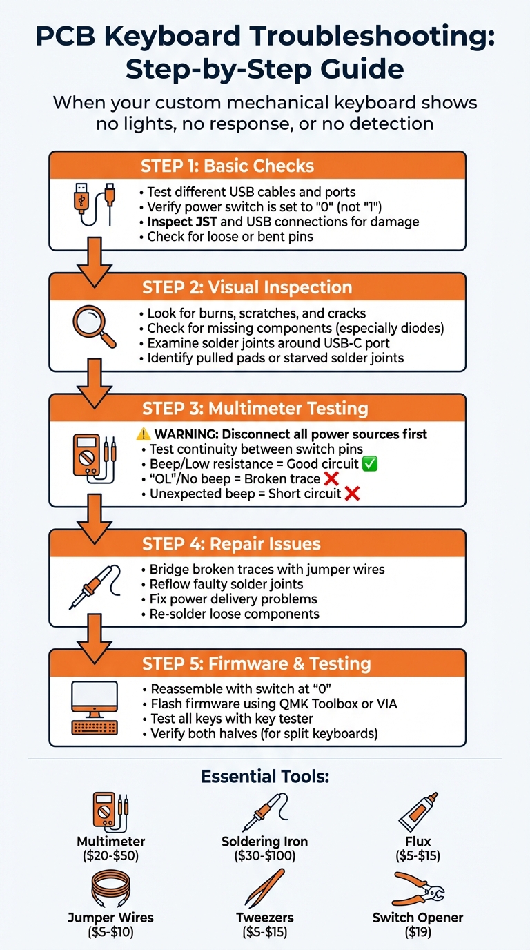
PCB Keyboard Troubleshooting Step-by-Step Flowchart
How to fix any soldered PCB mechanical keyboard with broken LED & Switches [Keychron K6]
sbb-itb-3cb9615
Basic Checks Before Troubleshooting
Before diving into advanced diagnostics with tools like a multimeter or soldering iron, start with simple connection checks. These quick steps often reveal common problems, like faulty cables or incorrect switch settings, that can mimic more serious issues.
Test Different USB Cables and Ports
Swap out the USB cable first. Some non-standard cables, particularly those designed for aesthetics, might not deliver enough power - especially for keyboards with RGB lighting. Additionally, some USB cables are "power only", meaning they lack the data lines needed for your computer to recognize the keyboard. To rule out cable issues, try a basic, short USB cable.
Plug directly into a motherboard USB port. Avoid using USB hubs, as they often fail to supply adequate power. Also, check the physical connection. If the cable feels loose or wobbly, the USB port itself could be damaged.
Once you've ruled out cable and port issues, move on to checking the PCB's power switch.
Verify PCB Power Switch Position
Custom keyboard PCBs often include a physical toggle switch on the back of the board. This switch toggles between "0" (normal use) and "1" (bootloader or DFU mode). If the switch is set to "1", your operating system won't recognize the keyboard as an input device.
Unplug the keyboard before adjusting the switch. Flip the PCB over and ensure the switch is set to "0." Sometimes, PCBs are shipped with the switch in the "1" position, or it might accidentally get moved during assembly. After setting it to "0", reconnect the keyboard to check if it's detected.
If the power switch is correctly positioned, inspect the board's physical connections next.
Check JST and USB Connections
For keyboards with a daughterboard, examine the JST cable for damage or misalignment. The male pins should be straight, and the cable should not have sharp bends or kinks. Ensure the JST cable fits securely into its header with no visible gaps.
Support the PCB header when handling JST cables. Applying pressure without supporting the female header can damage the board, such as lifting the header or breaking solder joints. Also, inspect both USB and JST connections for dirt, debris, or bent pins. Even minor damage, like a single bent pin, can prevent proper contact and cause the keyboard to fail.
| Component | Proper Functionality | Signs of Issues or Failure |
|---|---|---|
| USB Port | Firm connection; works at any angle | Loose connection; requires holding at an angle; bent pins |
| JST Cable | Straight wires; straight male pins | Kinks, sharp bends; bent pins in male connector |
| JST Header | Firmly soldered pins; straight alignment | Bent pins; header lifting from PCB |
| Power Switch | Set to "0" for normal operation | Set to "1" (Bootloader/DFU mode) |
| USB Cable | Short, basic data cable | "Power only" cable; overly long or decorative cable |
Inspect the PCB for Physical Damage
Once you've checked all connections and power settings, it's time to examine the PCB for any physical issues. Problems like scratches, cracks, or missing components can disrupt circuit paths and stop your keyboard from being detected. A careful visual inspection can often uncover issues that swapping cables alone can't resolve.
Look for Burns, Scratches, and Cracks
Inspect the PCB surface for scratches that might sever copper traces. Even a minor scratch, perhaps caused during assembly, can interrupt the electrical connection between components. Additionally, watch for cracks in the board itself, as these can sever multiple circuit paths at once, potentially causing rows or columns of keys to stop working.
Check for missing surface-mounted components, especially diodes. Each switch generally relies on a diode to register keypresses. If a diode is dislodged during shipping or assembly, it could result in a non-functional key or an entire row failing to work. Also, keep an eye out for burn marks or discoloration near components, which might signal overheating or electrical shorts.
Examine Solder Joints and Connector Pins
Beyond visible surface damage, it's essential to inspect the internal connections closely.
Review the solder joints around the USB-C port. Look for bent or misaligned pins, as these can disrupt data and power transmission entirely.
Check solder joints for signs of insufficient solder, often called "starved" connections. A proper solder joint should fully encase the pin and pad, appearing smooth and shiny. If it looks dull, cracked, or incomplete, it might be a cold solder joint, which hasn't bonded correctly. For hotswap boards, also verify that sockets are firmly attached to the PCB. If the internal metal "leaves" in the sockets are bent, they may fail to make proper contact with switch pins. As noted by CannonKeys:
A pad is the silver ring on the pcb that surrounds each switch pin. If that ring is gone, the pad is pulled.
Pulled pads break the electrical connection permanently and typically require trace repair to fix.
| Visible Sign | Potential Cause | Impact on Detection |
|---|---|---|
| Unstable USB-C Port | Physical strain or poor solder | Complete failure to be recognized by PC |
| Missing Diode | Impact or manufacturing defect | Specific key or row/column fails to register |
| Scratched Trace | Assembly mishap | Broken circuit path; multiple keys may fail |
| Pulled Pad | Forceful switch/socket removal | Permanent break in the circuit for that switch |
| Starved Solder Joint | Insufficient solder during assembly | Intermittent registration or complete failure |
Test Circuits with a Multimeter
To ensure your electrical connections are functioning properly, use a multimeter. This versatile tool helps measure voltage, resistance, current, and continuity, making it essential for diagnosing electrical faults. It acts as the bridge between visual inspections and pinpointing specific issues.
How to Test PCB Continuity
Start by disconnecting all power sources and waiting for any residual voltage to dissipate. As MorePCB cautions:
Testing a live PCB can not only lead to multimeter damage but also presents significant safety hazards, particularly with high-voltage circuits.
Switch your multimeter to continuity mode, typically represented by a soundwave icon or a diode symbol. Before testing, touch the probes together - if you hear a beep or see a display change, the multimeter is ready to use. Then, place one probe on a switch pin and the other on its corresponding connection point. A beep confirms a continuous path, while "OL" indicates a break in the circuit.
| Multimeter Reading | Meaning | Potential Keyboard Issue |
|---|---|---|
| Beep / Low Resistance | Continuous Path | Circuit is functioning properly. |
| No Beep / "OL" | Open Circuit | Could indicate a broken trace, cracked PCB, or cold solder joint. |
| Beep (unexpected) | Short Circuit | Possible solder bridge or damaged component. |
Find Broken Traces
Use the continuity test results to narrow down the fault. Start by identifying which keys aren’t working. For instance, if a specific section of keys (like I, O, and P) fails while others in the same row work fine, the issue likely lies between the last functioning key and the first non-functioning one. Use the multimeter probes to check the connection between these points. As noted in Bastard Keyboards Documentation:
No beep can be heard and no change is observed in the multimeter's display, yet the schematic demands these points are connected. The fault is confirmed.
If you're having trouble determining which switches should connect, use PCB design software like KiCad to review the schematics. This visual aid helps you locate where the circuit should be continuous and identify where the break has occurred.
How to Repair Common PCB Problems
After performing a visual inspection and multimeter tests, it's time to tackle common PCB issues like broken traces, faulty solder joints, and power delivery problems. With some basic tools and patience, these repairs can restore your keyboard's functionality before reassembly and testing.
Repair Broken Traces
Bridging is the go-to fix for broken traces. This involves soldering a jumper wire to bypass the damaged section of the PCB. If you don’t have access to schematics, you can identify the correct bridge points by comparing the broken trace with adjacent functioning keys. Once identified, strip a small section of wire, tin the ends, and solder it to the appropriate pads or component legs. This creates a new electrical connection that restores the circuit.
Re-solder Faulty Components
For components like USB ports or hotswap sockets that are intact but not working, reflowing the solder joint can often fix the issue. To reflow, heat the joint until the solder melts, then add a small amount of fresh solder if necessary to strengthen the connection. When working with diodes, which are polar components, use tweezers to hold them steady and ensure their orientation matches the PCB silkscreen. Once these connections are addressed, you can focus on power-related problems.
Fix Power Delivery Problems
If traces and solder joints are intact but power issues persist, the problem might lie with power delivery. Many keyboard issues are rooted in insufficient power rather than a broken circuit. Check the power configuration to ensure everything is set correctly, such as verifying the position of any physical DFU or bootloader switches.
| Symptom | Potential Power Issue | Recommended Fix |
|---|---|---|
| Keyboard disconnects when RGB is turned on | Insufficient current | Use a shorter cable; avoid USB hubs |
| No power/LEDs after assembly | Electrical short or reversed component | Inspect LED/MCU orientation; check for solder bridges |
| Device recognized as "Bootloader" | DFU switch position | Toggle the switch to "0" or "Use" position |
| Power only when cable is held at an angle | Damaged USB port | Reflow port pins or replace the USB connector |
| One half of split keyboard is dead | TRRS short or cold joint | Inspect TRRS jack soldering; ensure the cable is TRRS, not TRS |
Reassemble, Check Firmware, and Test
Put the Keyboard Back Together
When reassembling the keyboard, take care to support the female JST header while plugging in the cable. Make sure it clicks firmly into place. Also, double-check that the toggle switch is set to "0" for normal operation. If left in the "1" position, the keyboard will enter bootloader mode and won't function as an input device.
Reset or Flash the Firmware
If the keyboard isn’t detected after putting it back together, you may need to flash the firmware. To enter bootloader mode, press the reset button on the bottom of the PCB or hold down the Esc key while plugging in the USB cable. For split keyboards that haven’t been updated in a while (over two months), flash each half separately to ensure they can communicate properly.
For most keyboards, use QMK Toolbox (version 0.0.21 or newer). If you're on Windows and the device isn’t recognized in DFU mode, you’ll need to install the drivers through Tools > Install Drivers. If you’re working with RP2040-based boards like the Elite-Pi, flashing is as simple as dragging and dropping the .uf2 file into the "RPI-RP2" drive that appears.
"It is very important that you do not unplug the keyboard or otherwise interrupt the flashing process while the firmware is being written."
Here’s a quick reference for common bootloaders and flashing methods:
| Bootloader | Common Hardware | Flashing Method |
|---|---|---|
| ATmega32u4 DFU | Elite-C, most Keebio PCBs | Use QMK Toolbox "Flash" button |
| STM32 DFU | Proton C, Quefrency Rev. 6 | Use QMK Toolbox "Flash" button |
| Caterina | Pro Micro (Arduino) | Use QMK Toolbox "Auto-Flash" and double-tap Reset |
| UF2 | RP2040, Elite-Pi | Drag and drop file to USB mass-storage drive |
Once the firmware update is complete, verify that the keyboard is registering inputs as expected.
Test Keyboard Detection
After updating the firmware, confirm that the keyboard is functioning correctly. The keyboard should reconnect as an input device automatically. Use tools like QMK Configurator’s online key tester or VIA’s KEY TESTER tab to check that every switch registers properly. If a key doesn’t respond, try rebinding it to a common key like "A" in VIA to see if the problem is with the physical switch or the keymap.
For split keyboards, test each half individually via USB before connecting them with the interconnect cable (TRRS or USB-C). Then, test both halves together. Keep in mind that certain keys, like Fn or layer toggles, might not show up in standard key testers since their functions are managed by the firmware. Use VIA’s "Test Matrix" mode to confirm they’re working.
If the keyboard disconnects when you turn on the LEDs, this could point to a power delivery issue rather than a problem with the PCB. In this case, swap your custom cable for a basic USB cable plugged directly into a computer port to see if that resolves the issue.
Tools You Need for PCB Troubleshooting
Once you've identified possible issues with your PCB, having the right tools on hand can make diagnosing and fixing problems much easier. Beginners often start with simple items, like metal tweezers, to bridge switch pin pads and test key detection. This helps determine whether the fault lies with the switch or the PCB itself.
For more advanced troubleshooting, a multimeter is a must-have. Priced between $20 and $50, it helps check continuity, confirm power delivery, and pinpoint broken traces. A soldering iron with temperature control, costing around $30 to $100, is essential for reflowing weak solder joints or reattaching loose hotswap sockets. When reflowing, heat the solder until it turns liquid, hold for a second, and then gently remove the iron. To ensure clean, reliable joints, apply flux ($5–$15) sparingly - it improves solder flow significantly.
If you're dealing with broken traces or pulled pads, jumper wires ($5–$10) are invaluable. Always opt for insulated wires to avoid accidental shorts. Tweezers ($5–$15) are another versatile tool - they can bridge pads during testing, hold small components like diodes, or adjust hotswap leaves. For mechanical switch issues, the KFA Switch Opener ($19.00) is perfect for inspecting internal switch parts, such as leaves, to confirm functionality.
| Tool | Purpose | Price Range | Usage Tips |
|---|---|---|---|
| Multimeter | Testing continuity and checking circuits | $20–$50 | Use to identify broken traces or confirm power delivery |
| Soldering Iron | Re-soldering components and reflowing joints | $30–$100 | Ensure temperature control; hold on liquid solder briefly for a clean finish |
| Flux | Improving solder flow | $5–$15 | Apply sparingly to avoid mess and ensure solid joints |
| Jumper Wires | Fixing broken traces or pads | $5–$10 | Use insulated wires to prevent short circuits |
| Tweezers | Bridging pads and handling small parts | $5–$15 | Great for precise adjustments and holding tiny components |
| KFA Switch Opener | Opening and inspecting switches | $19.00 | Useful for checking internal switch components like leaves |
Beyond physical tools, software utilities are equally important for confirming PCB functionality. Free programs like QMK Configurator, VIA, and Karabiner-Elements allow you to test whether your PCB is sending the correct signals to your computer. For keys like Fn or layer toggles, which are managed by firmware, VIA's "Test Matrix" mode is particularly helpful since standard key testers might not detect them. These tools, combined with the diagnostic steps mentioned earlier, provide everything you need for effective troubleshooting.
Conclusion
Fixing PCB issues requires a step-by-step approach, starting with the basics and moving toward more involved diagnostics. Begin with simple checks: try different USB cables and ports, confirm the power switch is in the correct position, and inspect JST connections. Then, perform a physical inspection to look for visible problems like burns, cracks, or cold solder joints. Once the basics are covered, use a multimeter to test for continuity and identify broken traces. Repair these issues by reflowing solder joints or using jumper wires where needed.
Having the right tools makes all the difference when tackling these repairs. A dependable multimeter and a temperature-controlled soldering iron are must-haves for most PCB fixes. Metal tweezers can also come in handy for bridging switch pads, which helps determine if the issue is with the PCB or the switch itself.
Software tools are equally important. Programs like VIA, QMK Configurator, and Karabiner-Elements can help confirm your PCB is communicating correctly with your operating system. VIA's "Test Matrix" mode is particularly helpful for testing special function keys, such as Fn or layer toggles, which might not register in standard key testers. These tools streamline the troubleshooting process, reducing downtime and ensuring your keyboard works as intended.
If you're in need of components or tools for your repairs, KeebsForAll offers a wide selection of products. From the Freebird keyboard series (starting at $160.00) to maintenance items like Krytox 205 g0 lubricant ($7.95), they provide everything you need to keep your mechanical keyboard in top shape. Check out their full catalog at KeebsForAll.
FAQs
How can I tell if my USB cable is “power-only”?
To determine if a USB cable is power-only, try connecting a device to your computer. If the device charges but isn't detected by the computer or doesn't allow data transfer, the cable is probably designed for power only. Another way to check is by examining the cable's connectors - look for missing or damaged data pins. Power-only cables don’t have the necessary internal wiring for data transfer.
What should I check first if the keyboard shows up as “Bootloader” on my computer?
If your keyboard shows up as “Bootloader,” it might mean the PCB is in bootloader or DFU mode. To fix this, unplug the keyboard and check the switch on the back of the PCB (if your model has one). Make sure it's set to position 0, which is the normal operating mode. If it’s on position 1, flip it back to 0, then reconnect the keyboard. This usually clears up detection problems.
How can I tell if my keyboard issue is firmware-related or a physical PCB problem?
Start by carefully examining the PCB for any visible signs of damage. Look for things like loose connections, burn marks, or other physical faults that might stand out. These can often indicate what's causing the issue.
Next, test the hardware. Use a conductive tool (like tweezers) to check if the keys register properly. This step helps confirm whether the issue lies in the hardware itself.
If everything appears fine on the hardware side, try flashing the firmware. Tools like QMK Toolbox are great for this process. However, if the problem continues even after flashing the firmware, there's a good chance the PCB has a deeper physical defect.