When your keyboard stops working, the problem often lies in the PCB (printed circuit board). Issues like unresponsive keys, flickering RGB lights, or power failures can often be fixed without replacing the whole board. This guide walks you through the essential steps, tools, and techniques to troubleshoot and repair your keyboard PCB.
Key Takeaways:
- Common PCB Issues: Damaged traces, weak solder joints, faulty diodes, or firmware glitches.
- Tools Needed: Digital multimeter, soldering iron, desoldering tools, isopropyl alcohol, and anti-static equipment.
-
Steps to Troubleshoot:
- Start with a visual inspection for damage like burn marks or corrosion.
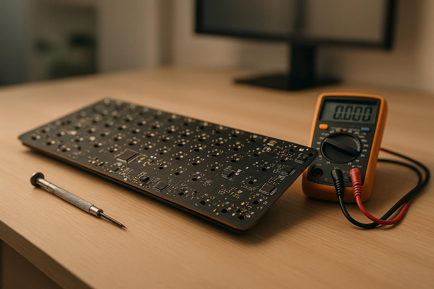
- Test electrical continuity using a multimeter.
- Check voltage levels and power flow.
- Inspect and repair components like diodes, switches, and USB connectors.
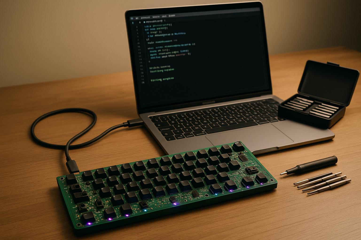
- Address firmware problems by reflashing or resetting.
- Workspace Setup: Use an anti-static mat, good lighting, and proper safety gear to prevent damage to sensitive components.
By following these steps, you can fix most keyboard PCB issues, save money, and extend the life of your keyboard. Ready to dive in? Let’s get started.
How to Fix a Keyboard (Circuit Board Trace Repair, Multimeter Tutorial, Conductive Paint)
Tools and Workspace Setup
Having the right tools and a well-prepared workspace can make all the difference between fixing your keyboard's PCB successfully or causing further damage. The right setup not only prevents mishaps but also saves you time.
Required Tools
To get started, you'll need a few essential tools. A digital multimeter is a must-have for checking voltage, resistance, and continuity. A reliable multimeter in the $30–$50 range should handle most tasks with ease. Pair this with a temperature-controlled soldering iron (25–40 watts is ideal for keyboard PCBs) and rosin-core solder in a 0.6–0.8 mm diameter for precise and effective soldering.
For removing components, keep both a desoldering pump and solder wick on hand. The pump creates a vacuum to remove melted solder, while the wick absorbs solder when heated. Each tool has its strengths, so having both ensures you're ready for different repair scenarios.
You'll also need precision tools for handling small components. Fine-tip tweezers, a precision screwdriver set, and a keycap puller are essential for disassembling your keyboard. If you're working on a hot-swap board, a switch puller will help you avoid damaging sockets. Tools like a switch opener and stem holder can also simplify switch modifications.
For cleaning, isopropyl alcohol (preferably 99% concentration) and lint-free wipes are excellent for removing flux residues and contaminants that might interfere with connections. A small brush can help you clean tight spaces around components.
If you're tackling more advanced issues, consider specialized tools. An oscilloscope can identify timing problems in key matrix scanning, while a thermal camera can pinpoint overheating components. While not necessary for most repairs, these tools are invaluable for diagnosing complex problems, especially in professional settings.
Finally, don't overlook safety. A solder fume exhaust fan is crucial for removing harmful vapors during soldering. Protect yourself further with chemical-resistant gloves, safety glasses or goggles, and a respiratory mask when working with potentially hazardous materials.
| Safety Gear | Purpose |
|---|---|
| Chemical-resistant gloves | Protects your skin from harmful substances |
| Disposable coveralls | Keeps clothes and skin free from contamination |
| Safety glasses or goggles | Shields your eyes from debris and chemicals |
| Respiratory mask | Prevents inhaling harmful fumes or dust |
Setting Up Your Workspace
Static electricity is one of the leading causes of PCB damage, so creating an ESD-safe workspace is critical. Start with an anti-static mat connected to a proper ground point and wear an anti-static wrist strap linked to the same ground. Store components in anti-static bags after handling them, and regularly test your anti-static equipment to ensure it’s functioning properly.
Good ventilation is a must - use fume extractors and maintain humidity levels between 40% and 60% to reduce static buildup.
Keeping your workspace tidy is just as important. Organize tools like multimeters, oscilloscopes, and soldering irons so they're within easy reach. Store small parts in labeled containers to avoid losing them during repairs. Good lighting is essential, too - an adjustable LED lamp with magnification can help you spot tiny traces and read markings more easily.
Before you start working, always disconnect power sources and discharge any capacitors to avoid electrical shocks and protect the PCB. A clean, organized workspace also prevents contamination and minimizes risks to the sensitive components of your keyboard.
For those looking to stock up on quality tools or replacement parts, check out KeebsForAll (https://keebsforall.com). They offer a wide range of mechanical keyboard parts and accessories designed with enthusiasts in mind, ensuring you have everything you need to handle PCB repairs effectively.
With your tools ready and workspace set up, you’re well-prepared to dive into PCB troubleshooting.
PCB Troubleshooting Steps
Diagnosing PCB issues systematically is crucial to pinpoint problems and address them before further damage occurs.
Visual Inspection for Damage
Start by disconnecting the power and taking anti-static precautions. Then, closely examine the PCB using a magnifying glass or USB microscope. Look for visible signs of damage, such as burn marks, discoloration, or components that seem out of place. Adjust lighting and angles to spot subtle defects like hairline cracks in solder joints or lifted pads.
Pay extra attention to solder joints. Cold joints often appear dull or grainy instead of smooth and shiny. Solder bridges, on the other hand, create unintended connections between pins or traces. Cracked joints may show as tiny fractures around leads, especially near larger components prone to thermal stress.
Check for missing or misaligned components, and ensure all components are installed with the correct polarity as per the schematic. Placing a component backward can lead to immediate failure when power is applied.
If you notice burn marks or discoloration, it’s a sign of overheating or electrical stress. These areas might smell burnt or show residue in brown or black. In such cases, you’ll likely need to replace the damaged component and repair the affected trace.
Testing Electrical Continuity
After the visual inspection, use a multimeter to test electrical continuity across the PCB. This step helps identify open circuits, short circuits, or poor connections that aren’t immediately noticeable.
Switch your multimeter to continuity mode (look for the soundwave or diode symbol). Place the probes on two points that should have an electrical connection. If the multimeter beeps, the connection is intact. If it doesn’t beep or displays 'OL,' the circuit is broken.
- Begin by checking key matrix connections. Press each switch and confirm continuity between its two terminals. Trace connections from the switch socket to the diode, then to the row and column traces. A lack of continuity could point to a damaged trace, broken via, or poor solder joint.
- Inspect USB connector pins to ensure proper connections to the PCB traces. Pay close attention to the data lines (D+ and D-), as they must maintain reliable continuity with the microcontroller. Power pins should connect seamlessly to their respective power rails.
- Test component connections by probing from component pins to their corresponding points on the PCB. Resistors, capacitors, and ICs should all show proper continuity. Make note of any irregularities.
You can also use the resistance mode on your multimeter for continuity testing. Zero resistance in traces and connections indicates they’re functioning correctly. Low resistance is acceptable, while infinite resistance (high readings) signals a broken circuit.
Once continuity is verified, move on to diagnosing power issues by testing voltage across key areas.
Voltage Testing and Power Problems
Power-related issues are among the most common causes of PCB failures. Incorrect voltage can damage components or cause them to malfunction, so verifying power delivery is a critical step.
Set your multimeter to voltage mode and measure the power rails, typically 5V from USB or 3.3V for the microcontroller. Compare the readings to expected values. For example, the main power rail should measure close to 5V (acceptable range: 4.8V to 5.2V). Similarly, the microcontroller’s power pins should align with its operating voltage - commonly 3.3V or 5V, depending on the chip.
Power distribution issues may show up as voltage drops under load or inconsistent readings across the board. Inspect decoupling capacitors near power-intensive components, as insufficient capacitance can cause voltage dips and erratic behavior.
For instance, a user reported a VCC reading of 0.6V with an overheating chip, which turned out to be caused by reversed polarity. Correcting the USB footprint resolved the issue.
Overheating components are often a sign of shorts or excessive current draw. If the microcontroller feels hot to the touch, a short circuit might be present, potentially requiring PCB replacement. Use freeze spray or a thermal camera to identify hot spots that aren’t immediately visible.
Finally, test ground connections throughout the PCB. All ground points should show continuity with each other and measure 0V relative to ground. Poor ground connections can lead to unpredictable behavior or communication errors.
When tackling power issues, don’t overlook potential firmware problems. Even a healthy PCB may seem faulty if the firmware is corrupted or improperly configured. A systematic approach to flashing and testing firmware can help differentiate between hardware and software issues.
sbb-itb-3cb9615
Common PCB Problems and Solutions
Systematic testing often uncovers a range of common PCB issues. Each problem typically comes with specific symptoms and requires targeted fixes to restore functionality.
Switch and Diode Problems
Issues with switches are among the most frequent problems, often showing up as keys that fail to register, ghosting, or inconsistent responses.
Bent switch pins are a frequent culprit, especially with hotswap sockets. If a switch stops working after removal, check the metal pins for bends. CannonKeys describes this issue well:
"Pins can bend when inserting a switch into a socket, and when removed you will be able to clearly see one of the pins bent. Straighten it with pliers gently, and then put back into the socket."
To fix bent pins, use needle-nose pliers and apply gentle pressure to avoid snapping them. Be cautious, as repeated bending can weaken the metal.
Loose hotswap sockets can lead to intermittent key registration. If the socket shifts when inserting or removing switches - or if a switch feels loose - reflow the solder on the PCB's underside to secure the connection.
Diode issues, such as missing or improperly oriented diodes, can disrupt the keyboard matrix. Diodes must be installed with the black band (cathode) aligned to the PCB marking. Test their functionality using the diode test mode on a multimeter. As CannonKeys explains:
"Put simply, diodes are needed for keypresses to register. Every single switch needs a diode to properly input. Fixing this requires a soldering iron and solder. The orientation of diodes is specific, they will only work in one direction."
When replacing diodes, 1N4148 diodes are a reliable choice for most keyboards. Solder them flush to the PCB and confirm their orientation before applying heat.
While hardware problems are common, software and firmware issues can also cause similar disruptions.
Firmware and Software Problems
Firmware-related issues can sometimes mimic hardware failures. These problems often arise from failed firmware updates, power interruptions during flashing, or experimenting with custom layouts.
Unresponsive PCBs that fail to appear in Device Manager or show up as unknown devices may indicate firmware problems. Check if your PCB has a reset button or DFU switch. Many modern PCBs include a small button to activate bootloader mode.
If the PCB enters DFU mode (e.g., showing as 'ATm32U4DFU'), you can reflash the firmware using QMK Toolbox. For boards compatible with VIA, use its interface to restore the default keymap.
Physical damage to the PCB itself can also lead to performance issues.
Damaged Traces and Broken Pads
Physical damage, such as cracks in traces or broken pads, is another common cause of PCB failure. Proto Express highlighted in December 2022 that thorough visual inspection is crucial for identifying such defects.
Damaged traces often appear as hairline cracks, complete breaks, or burned copper pathways. Use a magnifying glass or USB microscope to trace the path from a non-functional switch back to the microcontroller. Pay extra attention near mounting holes or flex points, as these areas are prone to stress.
For minor trace damage, conductive paint can be an effective fix. Clean the area with isopropyl alcohol, apply the paint with a fine brush, and let it cure before testing. For more severe damage, jumper wires are a reliable option. Use a thin, insulated wire (e.g., 30 AWG wire-wrap wire) to bypass the damaged trace. Scrape off the solder mask at both ends of the damaged section to expose clean copper, then solder the jumper wire directly to the trace. Be sure to route the wire carefully to avoid interference with other components.
Lifted pads occur when excessive heat or mechanical stress causes the copper pad to detach from the PCB. If a pad is entirely removed, locate the nearest connection point - such as an adjacent via or component lead - and solder a thin wire to reestablish the connection.
For broken switch pads, you can often bypass the issue by connecting directly to the corresponding diode or matrix traces. Refer to the PCB's schematic to identify the row and column lines, then create jumper connections to restore functionality.
If multiple traces or pads are damaged, consider whether the repair is worth the effort compared to replacing the PCB. However, for rare or discontinued boards, even extensive repairs may be worthwhile to preserve a unique keyboard.
Advanced Troubleshooting Methods
After covering the basics like visual inspections and electrical tests, advanced troubleshooting dives deeper, focusing on components like JST cables and daughterboards. These elements are crucial for maintaining strong connections and resolving persistent issues.
Checking JST Cables and Daughterboards
Most modern keyboards rely on JST cables to connect the main PCB to a daughterboard, which typically houses the USB connector. Diagnosing problems in this area involves a series of careful steps:
- Inspect the JST cable connectors: Unplug the cable and examine both ends for bent pins. If you spot any slight bends, carefully straighten them using tweezers.
- Verify wiring alignment: Check that the wiring matches on both ends of the cable, ensuring each pin is properly connected.
- Re-insert the cable properly: Plug the cable in evenly to avoid damage, and make sure it’s fully seated in its port. Test the USB connection with different cables and ports to rule out external issues.
- Look for physical damage: Examine the cable for kinks, sharp bends, or other signs of wear that could indicate an internal break.
- Check soldering on JST pins: Make sure all pins are securely soldered to avoid intermittent connections.
- Consider replacing the daughterboard: If the PCB still isn’t detected, try swapping out the USB-C Unified C3 daughterboard. Keep in mind that thicker boards may complicate case assembly.
These steps build on earlier diagnostics to ensure that the connections between the PCB and daughterboard are solid. While basic tests focus on individual components, these advanced methods address potential interconnectivity issues, providing a more thorough approach to troubleshooting.
Summary and Resources
Troubleshooting PCBs for mechanical keyboards doesn't have to be overwhelming. By following a structured process, you can save time and effort while pinpointing issues effectively.
Key Troubleshooting Steps Overview
The process starts simple and gradually moves to more detailed testing. Begin with a visual inspection to check for physical damage, such as burnt components or broken traces. From there, use tools like multimeters to test continuity and voltage, ensuring the circuits are intact. If specific keys or functions aren't working, focus on diagnosing individual components based on the symptoms you've observed.
For more complex issues, such as keyboard detection failures, turn your attention to interconnection components like JST cables and daughterboards. These parts handle USB connections, and faults here often lead to the keyboard not being recognized at all.
An organized workspace plays a big role in successful troubleshooting. Use ESD-safe tools, such as wrist straps or anti-static mats, to protect sensitive components. Good lighting is crucial for spotting tiny imperfections, and keeping tools neatly stored in anti-static containers ensures efficiency and safety.
Once you've identified the faulty components, the next step is finding reliable replacement parts.
Where to Find Replacement Parts
After diagnosing the problem, sourcing high-quality components is essential for a successful repair. KeebsForAll is a trusted supplier offering PCBs, switches, keycaps, and other mechanical keyboard parts. They emphasize quality and maintain a strong inventory to meet the needs of the keyboard community.
When choosing a replacement PCB, compatibility is key. Double-check that the dimensions and mounting points match your keyboard's case and plate. Additionally, decide whether you need a PCB with hot-swappable sockets or one designed for soldered switches, as this will impact your options.
PCBs with programmable firmware support, such as QMK or VIA, are a great choice. These systems allow for key remapping and macro programming, giving your keyboard added functionality beyond just the repair.
Aside from PCBs, you may need other common replacement parts like switches, diodes, USB-C connectors, JST cables, and hotswap sockets. These components often bear the brunt of wear and tear, so it's smart to keep a small stockpile on hand for future repairs.
FAQs
How can I tell if my keyboard has a PCB issue, and how is it different from other problems?
If your keyboard is showing signs like unresponsive keys, keys that register incorrectly or multiple times, or power issues such as random power loss, the problem might lie with the PCB. In more extreme cases, you might even spot burn marks or signs of overheating on the PCB.
To figure out if the issue is truly with the PCB, look for electrical faults - things like damaged traces, broken solder joints, or grounding problems. These are telltale signs of PCB trouble. On the flip side, issues like a sticky key or an uneven key feel are more likely caused by physical switch wear or dirt buildup. Pinpointing the exact cause will help you decide whether the PCB needs repair or if it’s a mechanical problem that requires attention.
How do I safely use a multimeter to check continuity and voltage issues on my keyboard's PCB?
To safely test your keyboard's PCB with a multimeter, start by setting the device to the appropriate mode: either continuity or voltage.
- Continuity testing: Place the probes on two points where a connection should exist. A beep from the multimeter indicates the circuit is complete.
- Voltage testing: Attach the positive probe to the power input and the negative probe to the ground. Once the PCB is powered on, the multimeter will display the voltage. This reading should align with the expected input value.
Make sure the multimeter is configured correctly to prevent damage to both the device and the PCB. Also, avoid direct contact with live circuits to reduce the risk of electrical shock. Following these steps will allow you to safely diagnose and address any issues with your keyboard's PCB.
What advanced tools and techniques can help diagnose tricky PCB issues in mechanical keyboards?
When dealing with tricky PCB problems in mechanical keyboards, having the right tools can make all the difference. Instruments like oscilloscopes, LCR meters, and IV tracers are incredibly useful for examining signal integrity and observing how components behave in real time. You can also rely on techniques like in-circuit testing (ICT) or JTAG debugging to pinpoint faults and handle complex programming tasks with precision.
For issues that aren't visible during a simple visual inspection, methods like X-ray inspection and automated optical inspection (AOI) come into play. They’re perfect for uncovering hidden problems - think internal cracks or solder joint failures - that might otherwise go unnoticed. These advanced approaches provide a more thorough and accurate way to troubleshoot, making them indispensable for tackling those hard-to-find PCB issues.


![[Pre-Order] Autumn Leaves PBT Keycaps - KeebsForAll](http://keebsforall.com/cdn/shop/products/DSC09732.jpg?v=1676148273)


Leave a comment
This site is protected by hCaptcha and the hCaptcha Privacy Policy and Terms of Service apply.